


Fundamental Gas Testing Principles and Detection Physics
Gas testing instruments operate on well-established physical and electrochemical principles that translate molecular interactions into quantifiable electrical signals. At their core, these devices rely on selective recognition of target analytes—whether toxic, combustible, or volatile organic compounds—through controlled interaction with sensing elements. The gas testing principle hinges on three interdependent pillars: selectivity (distinguishing target gases from interferents), sensitivity (detecting low-concentration analytes), and reproducibility (delivering consistent output under identical conditions). In accuracy-critical environments such as petrochemical process units, refinery flare stacks, and accredited analytical laboratories, deviations exceeding ±2% of reading can compromise safety integrity systems or invalidate regulatory compliance reports—including those required under OSHA 1910.120, EPA Method 21, or IEC 61508 SIL-2 mandates.
Electrochemical Sensors: Selective Redox Reactions at Ambient Conditions
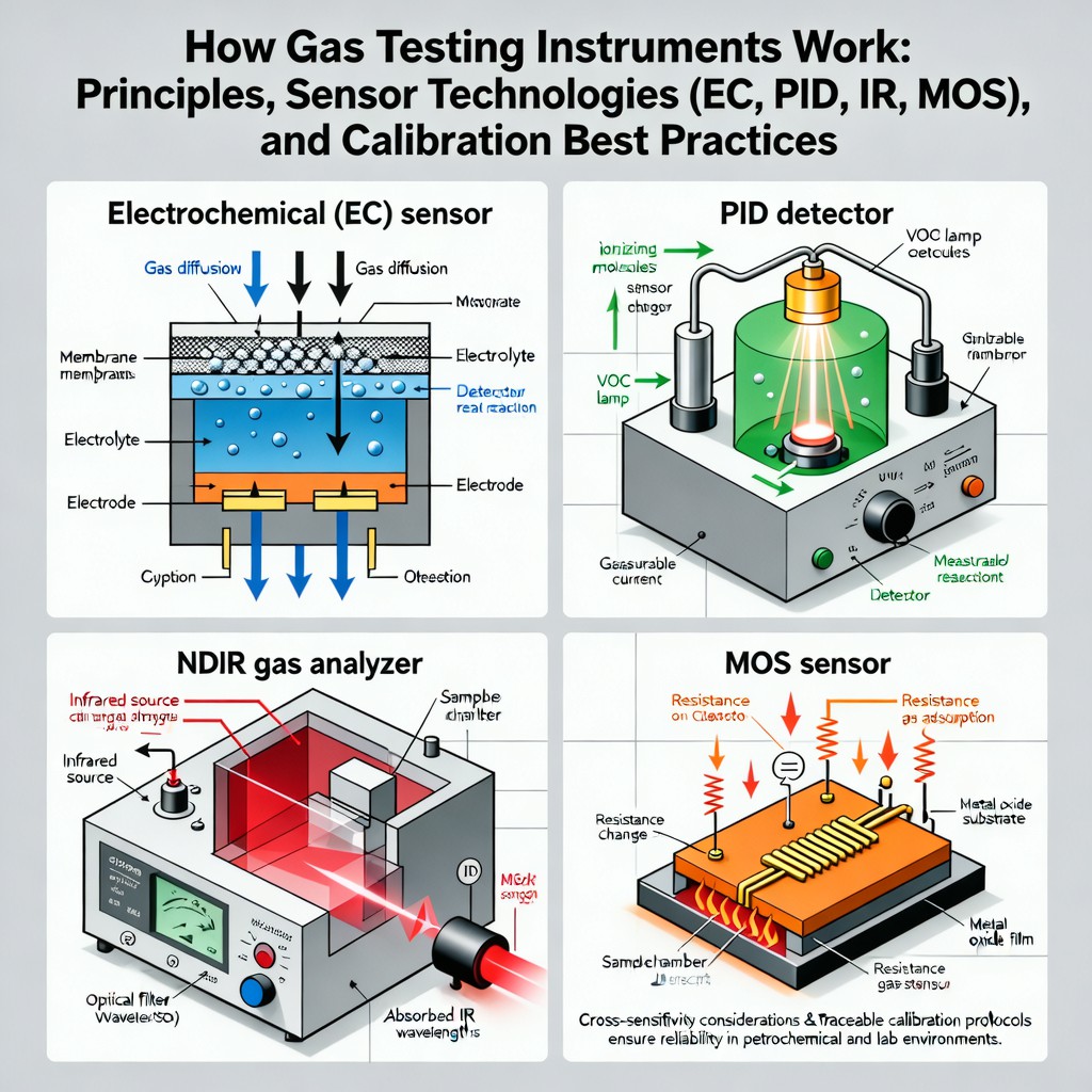
Electrochemical sensors exploit reversible oxidation-reduction reactions occurring at a three-electrode system immersed in an ion-conducting electrolyte (typically aqueous or polymer-based). When target gas diffuses through a hydrophobic membrane into the sensing chamber, it undergoes catalytic oxidation or reduction at the working electrode, generating a current proportional to concentration (Faraday’s law). Common configurations include amperometric (e.g., for CO, H2S, Cl2) and potentiometric (for O2, NOx). Critical performance parameters include response time (T90 typically 15–45 s), zero drift (<2% FS/month), and cross-sensitivity—for instance, SO2 may interfere with NO2 detection due to overlapping redox potentials. Modern designs incorporate temperature-compensated reference electrodes and dual-filter membranes to suppress humidity-induced signal attenuation and mitigate poisoning from silicone vapors or H2SO4 condensate.
Photoionization Detectors (PID): Ultraviolet Excitation and Electron Emission
PID detectors utilize high-energy ultraviolet photons (typically 10.6 eV, 10.2 eV, or 8.4 eV lamps) to ionize volatile organic compounds (VOCs) and certain inorganic species (e.g., NH3, PH3) possessing ionization potentials below the lamp photon energy. Ionized molecules release electrons captured by a charged collector electrode, producing a microampere-scale current linearly related to gas concentration over a dynamic range of 1 ppb to 10,000 ppm. Unlike broad-spectrum IR methods, PID offers superior sensitivity to aromatics, ketones, and terpenes—but suffers from inherent non-specificity: isobutylene-equivalent calibration requires compound-specific correction factors (CFs) published by manufacturers (e.g., CF = 0.5 for formaldehyde, 2.0 for benzene). Lamp fouling, window transmission loss, and humidity-dependent quenching (>70% RH reduces signal by up to 30%) necessitate routine optical maintenance and humidity compensation algorithms.
NDIR Gas Analyzers: Molecular Absorption Spectroscopy in the Infrared Band
Non-Dispersive Infrared (NDIR) gas analyzers apply Beer-Lambert absorption spectroscopy using broadband IR sources and narrowband optical filters aligned with fundamental vibrational-rotational absorption bands—e.g., CO2 at 4.26 μm, CH4 at 3.3 μm, and SF6 at 10.6 μm. Dual-beam architectures employ active and reference detectors to cancel out source aging, dust deposition, and thermal drift. Advanced NDIR systems integrate MEMS-based tunable filters or pulsed IR LEDs synchronized with lock-in amplifiers to achieve sub-ppm detection limits and<1% cross-sensitivity against common interferents like water vapor (mitigated via spectral subtraction or chilled-mirror drying). Response times are typically 1–5 s for flow-through configurations, making NDIR ideal for continuous emissions monitoring (CEMS) and confined-space entry verification where real-time stability and long-term zero stability (<±0.5% FS/year) are paramount.
Metal Oxide Semiconductor (MOS) Sensors: Surface Conductivity Modulation
MOS sensors operate by measuring changes in electrical resistance of heated metal oxide films (SnO2, ZnO, WO3) upon adsorption and surface reaction of reducing or oxidizing gases. Target molecules alter electron depletion layer thickness at grain boundaries, modulating bulk conductivity—often by orders of magnitude. While cost-effective and robust for broad-range combustible gas detection (e.g., LEL monitoring), MOS sensors exhibit pronounced temperature dependence (optimal operating range: 200–400 °C), slow recovery kinetics (Trecovery > 60 s), and high cross-sensitivity to ambient humidity, ethanol, and hydrogen. Recent advances include doped nanostructured oxides (e.g., Pt-SnO2) and integrated microheaters enabling pulsed-operation modes to discriminate between interfering species via transient resistance profiling—a technique increasingly adopted in smart multi-gas portable detectors compliant with EN 50104 and UL 2075 standards.
Calibration Best Practices: Traceability, Interval Management, and Uncertainty Budgeting
Calibration is not a one-time event but a metrological chain ensuring measurement traceability to national standards (e.g., NIST SRM 1861 for methane, NIST SP 260-124 for VOC mixtures). Best practices mandate use of certified calibration gases with stated expanded uncertainty (k = 2), verified by independent analysis (GC-FID or GC-MS), and delivered via precision mass flow controllers. Frequency must be risk-based: daily bump tests for life-safety instruments (per OSHA 1910.137), full calibration every 30–90 days depending on exposure history and sensor type, and annual third-party verification for CEMS-grade analyzers. Documentation must include pre-/post-calibration readings, zero/span drift values, environmental conditions (T, P, RH), and uncertainty contributions from gas standard purity (±0.3%), analyzer repeatability (±0.5%), and pressure/temperature compensation residuals (±0.2%). For SIL-rated systems, calibration procedures must align with IEC 61511 Annex H requirements for proof test coverage and diagnostic coverage assessment.
创作声明:内容由AI基于参考资料创作生成,请仔细甄别。