


Core Working Principle of Precision Digital Calipers
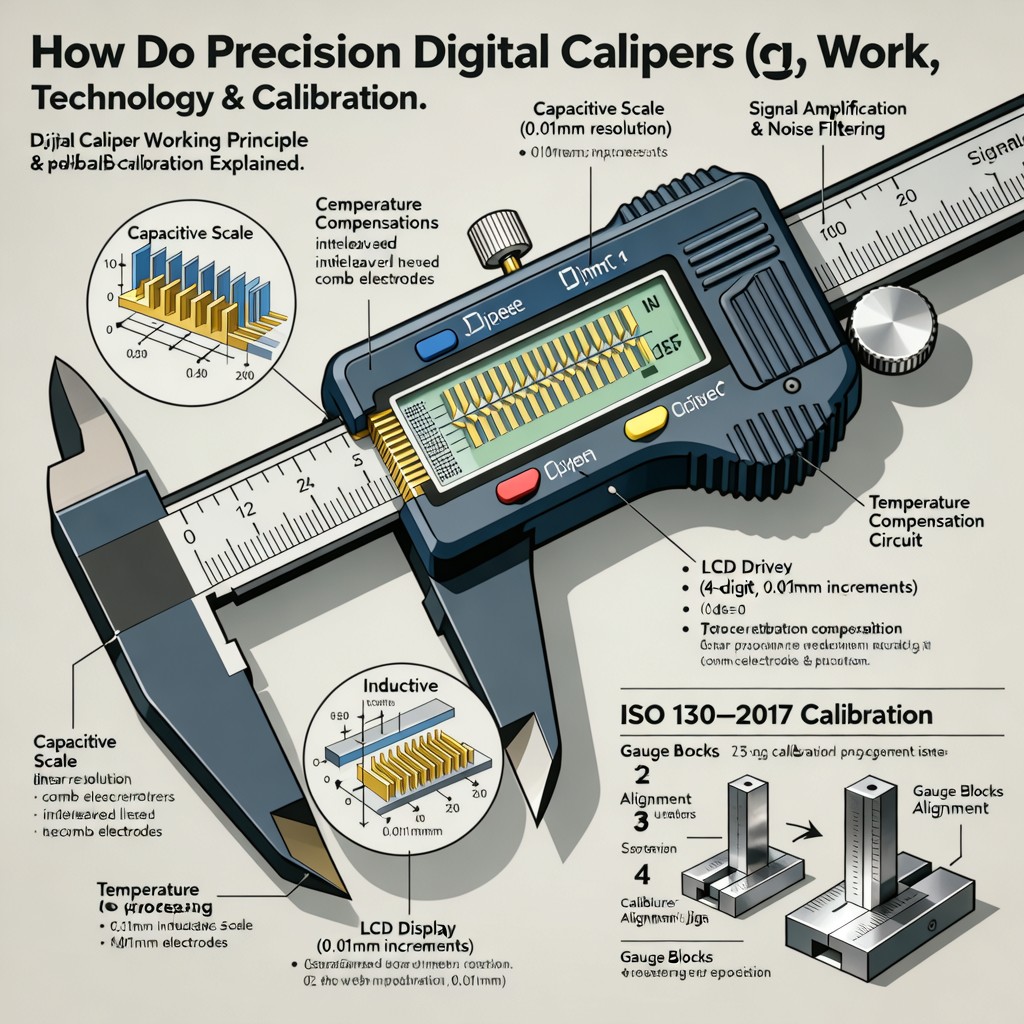
Precision digital calipers operate on the fundamental principle of converting mechanical linear displacement into a precise digital measurement through an integrated electronic scale system. At the heart of this process lies a high-resolution position-sensing mechanism—typically either capacitive or inductive—embedded along the main beam. As the movable jaw slides, it alters the physical relationship between sensor elements (e.g., overlapping electrodes or coil coupling), generating a measurable change in capacitance or inductance. This analog variation is continuously sampled by an on-board analog-to-digital converter (ADC), synchronized with a reference clock to ensure temporal accuracy and minimize jitter-induced errors.
Capacitive vs Inductive Scale Technologies
Capacitive scales utilize a patterned conductive grid on the beam and a corresponding read-head electrode array on the slider. Displacement modulates mutual capacitance between adjacent electrodes, producing sinusoidal signals whose phase and amplitude encode absolute position. These systems offer exceptional resolution (commonly 0.01 mm or better) and low power consumption but are sensitive to dust, moisture, and dielectric contamination on the scale surface. In contrast, inductive scales rely on eddy-current interactions between a coil-based read head and a ferromagnetic scale strip. They provide superior environmental robustness—resisting oil, coolant, and particulate ingress—while maintaining sub-10 µm repeatability. However, inductive systems typically require higher drive current and exhibit slightly lower native resolution than capacitive counterparts, often compensated via interpolation algorithms.
Signal Processing & Environmental Compensation
Raw sensor output undergoes multi-stage digital signal processing (DSP) within the microcontroller unit (MCU). First, noise suppression filters (e.g., adaptive FIR or Kalman filters) remove high-frequency interference from motor drives or electromagnetic fields. Then, quadrature decoding resolves direction and fine increments; advanced models apply real-time thermal drift compensation using onboard temperature sensors (±0.1 °C accuracy) and material-specific expansion coefficients for the beam (e.g., stainless steel α ≈ 10.8 × 10⁻⁶/°C). Humidity and barometric pressure are not directly measured but accounted for indirectly via factory-derived environmental correction tables validated across ISO 1 metrology labs.
LCD Display Resolution & User Interface Logic
The LCD display’s effective resolution is determined not solely by pixel count but by the combination of sensor resolution, internal interpolation, and firmware rounding logic. Most industrial-grade calipers support dual-mode display: metric (0.01 mm) and imperial (0.0005 in), with automatic unit conversion preserving full significant digits. The displayed value reflects a time-weighted average over 16–32 consecutive samples to suppress vibration-induced fluctuations. Zero-setting (absolute or relative) triggers a hardware latch that stores the current offset in non-volatile memory (EEPROM), ensuring retention after power cycling. Contrast and backlight intensity are auto-adjusted based on ambient light readings from an integrated photodiode.
ISO-Aligned Calibration Procedure
Calibration must conform to ISO/IEC 17025 and follow traceable protocols aligned with ISO 13028 and VDI/VDE 2622 Part 4. The procedure begins with thermal stabilization: the caliper and master artifacts (e.g., grade 0 gage blocks per ISO 3650) are conditioned at 20 °C ±0.5 °C for ≥4 hours. Five verification points are selected across the full range (e.g., 0 mm, 25 mm, 50 mm, 75 mm, 100 mm), each measured six times under consistent jaw contact force (1.5–2.5 N, verified with calibrated force gauge). Systematic error is calculated as the mean deviation from certified values; repeatability is expressed as standard deviation. If error exceeds ±0.02 mm (for 150 mm calipers), adjustment is performed via firmware offset correction using proprietary service mode—never mechanical re-alignment. Post-adjustment verification includes hysteresis testing (forward/backward traversal) and linearity assessment via least-squares regression (R² ≥ 0.9999).
Battery Life Considerations & Power Management
Modern digital calipers employ ultra-low-power MCU architectures (e.g., ARM Cortex-M0+), consuming<10 µA in sleep mode. A standard CR2032 lithium coin cell typically delivers 1.5–2 years of intermittent use (≈10 minutes active time per day), assuming auto-off activation after 10 minutes of inactivity. Battery voltage is monitored continuously; below 2.4 V, the display flashes “BATT” and measurement accuracy degrades due to reduced ADC reference stability. Unlike analog instruments, digital calipers do not fail catastrophically when battery weakens—instead, firmware enforces graceful degradation: disabling backlight, reducing sampling rate, and ultimately locking out measurements until replacement.